Architecture
Compared to PlatoSim v2, PlatoSim v3 has been rewritten from scratch in order to get rid of historical baggage and inefficient code constructions that had been built up for years. We have in particular minimised the dependencies to external libraries and replaced inactive libraries with code that is still actively maintained. As part of a healthy software development, our software now also includes an object-oriented design and proper unit testing.
The core software of PlatoSim is written in C++ but is best controlled and configured through our built-in Python interface. The goal of PlatoSim’s C++ code is to model a part of one CCD of a single camera on the platform - we refer to this as the CCD subfield. On this page we give an detailed describtion of the remaining building blocks and the steps that are executed during a simulation.
General overview
The design of the PlatoSim started from the concept displayed in Fig. 1. The main hardware components that make up the PLATO spacecraft are the platform, (telescope), camera, and detectors, all of which are represented by a separate class in PlatoSim. Since we are simulating noise features on an image taken from the sky, we added the Sky class to the concept. All these components are controlled by a Simulation object.
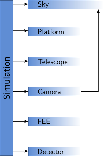
Fig. 1: Simulation object controlling classes.
Conceptual design
The more detailed design of PlatoSim is depicted in Fig. 2. The Simulation class in the center controls the process and knows about all the main components in the system.
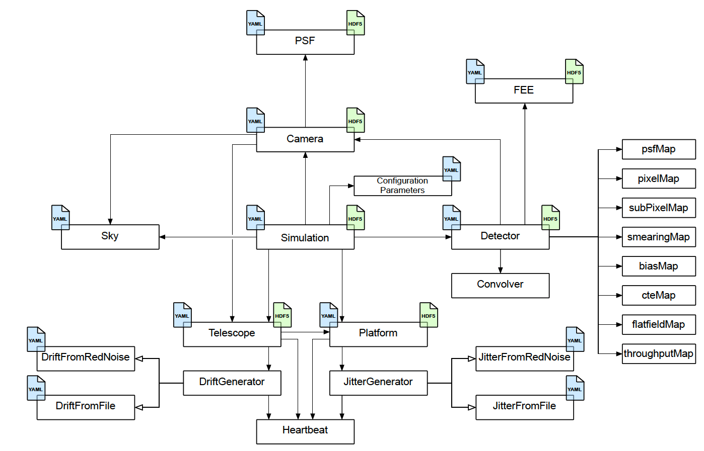
Fig. 2: Detailed conceptual design.
Each of these main components has its own set of responsibilities:
Platformprovides information about the pointing and the jitter,Telescopecontrols the thermo-elastic drift of the cameras,Cameraprovides information about the Point Spread Function (seePSFsubclass),Detectorcontrols all the different (sub)pixel maps.FEEcontrols the readout procedure and parameters for the electronics,
The blue file icons, attached to several boxes, indicate that information about its responsibility is provided in the YAML configuration file, while the green file icons indicate that the component is writing information to the HDF5 output file.
Control flow
Each PlatoSim simulation can be divided into two parts that happens sequential in time as shown in Fig. 3. Upon execution, PlatoSim first (a) read the configuration YAML file and initialises the Simulation object with these parameters. It further sets up the random red noise generators, if requested by the user. Next (b) the actual computation of the pixel images begins. This happens in a loop over the number of exposures that is requested in the YAML configuration file.
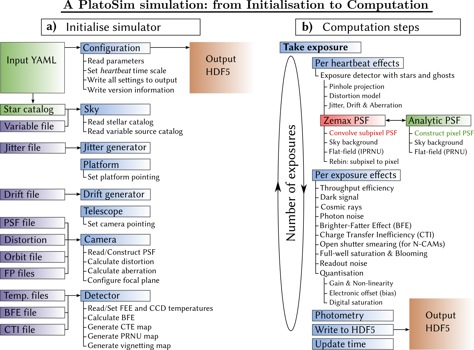
Fig. 3: Initialisation and execution of PlatoSim.
The two main steps in the simulation process are the integration of the light on the detector and the readout process. The computational steps are essentially divided into those phenomena who need to be tracked on a time scale much shorter than the exposure time (i.e. defined by PlatoSim’s heartbeat), and those phenomena that with good approximation can be modelled once per exposure.
Note that PlatoSim is completely modular, meaning that all effects can be switched on or off in the YAML configuration file using either yes (True) or no (False), respectively. After processing each exposure, the requested pixel maps are written to the output HDF5 file together with the photometric data if enabled in the YAML configuration file. Details about detected stars, their positions, and the pointing information is finally written to the output HDF5 file. For more details about each effect implemented in PlatoSim, please consult the PlatoSim paper.